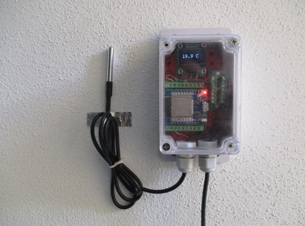
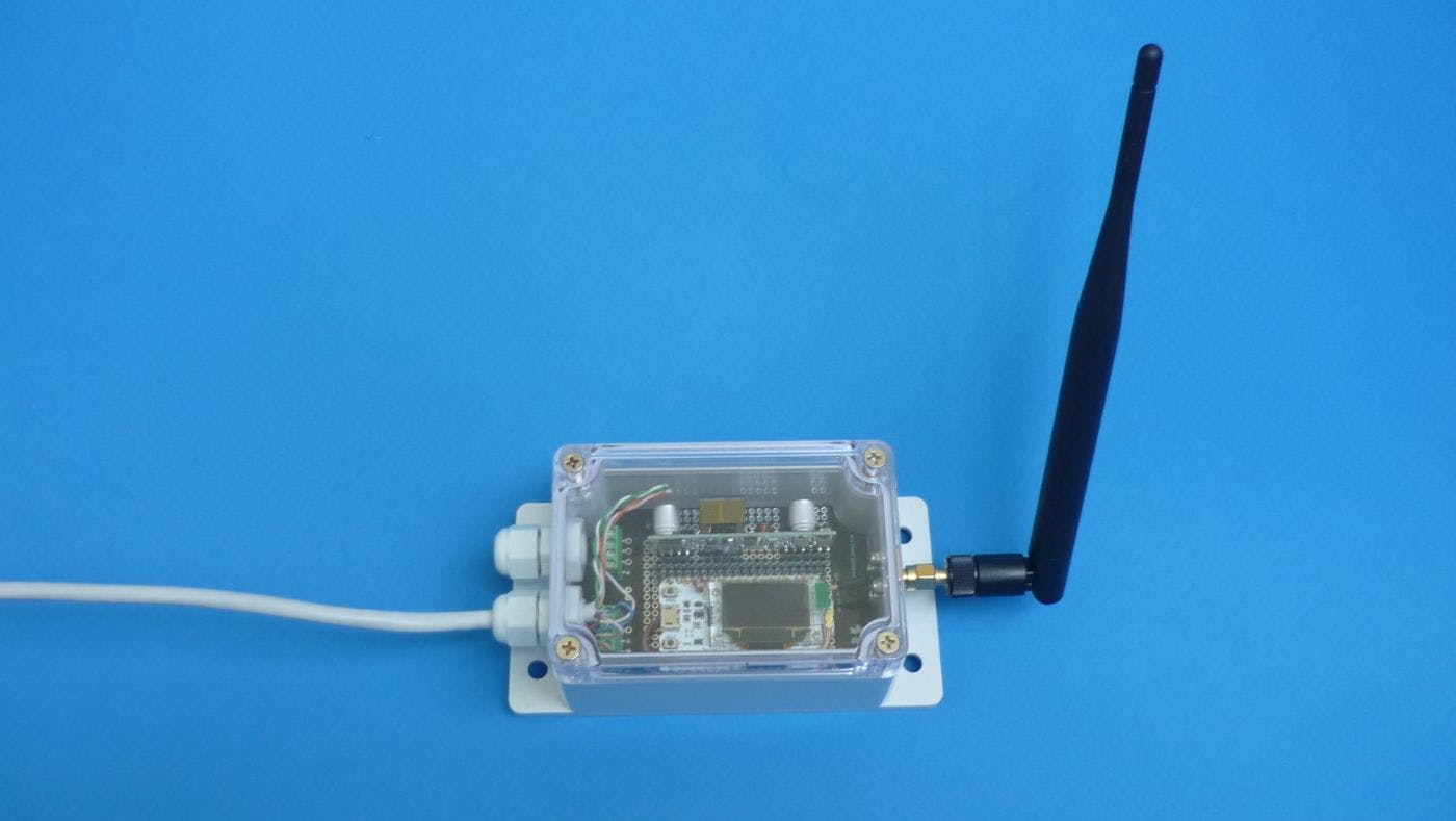
Software no-code/low-code platforms made it possible to create applications, writing only a few lines of code, and in some cases, ¡no code at all!. This reduces development effort and deployment time. This project combines two ideas: no-code/low-code software platform and a quick, robust prototyping system that requires no soldering. In this spirit, it is possible to move from an idea, to a materialised device working in a real environment in a few hours. Key component: ESP 32 D1 MINI Quick, robust hardware-software prototyping The following application will be built as an example: a WiFi thermometer based on ESP32, DS18B20 temperature sensor, and local I2C indicator. All this enclosed in a waterproof, wall-mountable box and powered by 5V. This will be accomplished using the following projects: HARDWARE: Quick, Open Source, robust prototyping system: MISISTEMITA SOFTWARE: Tested and also . TASMOTA ESPHome Bill of materials Component Datasheet - Buy link. - ESP32 D1 MINI buy it OLED 0.96 I2C Display DS18B20 waterproof temperature sensor 1/4W 1% TH Resistor Generic waterproof “Sonoff” enclosure 100x68x50mm Components needed to build the required misistemita modules. Component Datasheet - Buy link. Reverse locking nylon spacer M2.6 B-type self-tapping screw 3.5mm kf350 screw terminal (2,3 pins) for PCB 2.54mm female header connector Printed circuit boards needed to build the required misistemita modules PRINTED CIRCUIT BOARD SOURCE FILES REPOSITORY - BUY LINK A06 - Backplate for generic waterproof 100 x 68 x 52 mm enclosure B02 - 3.5mm screw terminal 2x7 connection board C12 - 3.5mm screw terminal breakout for ESP32 D1 MINI C10 - 3.5mm screw terminal breakout for I2C display SOFTWARE REPOSITORY - DOWNLOAD LINK ESPHome - download TASMOTA - download Hardware assembly Soldering will not be required* if the modules to be used have been built or acquired beforehand. The first step is to locate the boards in the backplate, as good practice, the should be placed somewhere on the edge of the backplate and as close as possible to the cable entry point. screw terminal wire connection boards The second step is to wire the different modules depending on the originally proposed project. Both solid copper cable and multi-stranded copper cable can be used. Downloading a minimum test firmware is recommended to test the connectivity of the components. The third step is to remove the external connections, locating the backplate in the enclosure and securing it with self-tapping screws. Pass the power cables through the cable glands and reconnect them to the board. The final step consists of closing the cover, adjusting the cable glands, and installing on the wall. Firmware setup The following points are not intended to be a comprehensive installation or configuration guide. For more information, refer to the documentation of each platform used, ( and ). Briefly, some hints about how the sensor was created on each of them will be presented. Tasmota ESPHome Tasmota The philosophy of Tasmota consists of a basic pre-compiled firmware that is downloaded to the device and once downloaded it is customized using templates. The Tasmota installer is based on a web browser, so no additional software is required. The following parameters were used: Base Firmware: Display Template setup: I2C port pins, DS18B20 sensor pin Display mode: 0 Display type: SSD1306 Temperature visualization rule: rule 1 ON DS18B20#Temperature DO Displaytext[zs2y20] %value% C ENDON ESPHome The philosophy of ESPHome consists of compiling a custom firmware using a YAML configuration file. This means that Home Assistant needs to be installed, and once it’s up and running, ESPHome should be installed as an add-on. After these two steps, it’s already possible to create sensors. A part of the configuration file is shown here in the most significant sections. # GPIO setup dallas: - pin: 26 i2c: sda: 21 scl: 22 # Sensor setup sensor: - platform: dallas address: 0x8c01131b44162184 id: outside_temperature name: "External temperature" font: # gfonts://family[@weight] - file: "gfonts://Roboto" id: roboto size: 20 display: - platform: ssd1306_i2c model: "SSD1306 128x64" address: 0x3c lambda: |- it.printf(90, 35, id(roboto), TextAlign::BASELINE_RIGHT , "%.1f °C", id(outside_temperature).state); End result hardware: The assembly of the hardware, starting from pre-built modules, took approximately one hour. firmware: Sensor firmware setup, using Tasmota, took approximately 10 minutes. Making a change to configuration like an I/O pin or visualization rule takes approximately 1 minute. The same task, using ESPHome, took approximately 2 hours the first time, because Home Assistant needs to be installed (On a Raspberry Pi or other computer). Once ESPHome is installed Making a change in configuration takes around 5 to 10 minutes depending of the speed of the Rpi for code compilation. On both platforms, the first setup is wired (ESP32 connected to a PC). After that all updates are done wirelessly (OTA). The only “code” that was typed on both platforms was the minimum necessary to visualize temperature on the I2C display. Each platform has its own way to do that. In both cases, has been just a single line. Also published . here